Page 1 of 2

Cutout and Regulator tests and adjustments

Posted: Wed Aug 01, 2012 2:06 pm
by birddog
Attention:
What I show here as to the adjustments of a Cutout or Regulator is what I have had success with in the past. The experts will tell you that only those with the training and equipment should attempt to adjust them. Also it is the opinion of some experts that if there is a malfunction, the unit probably has reached it’s expected life and should be replaced.


This may be true but we all can’t afford to replace parts at will. I have had good luck with cleaning and adjusting them. One thing to remember though, my tractors see only limited use. If you run yours on a regular basis the cleaning and adjustment may not last long.

The Cutout Test and Regulator Test as I show them is a bench type test. It can be done while mounted on your Cub, but all wires should be removed. Remember to insulate them so they don’t short out. After making your adjustments and it seems to be working, at the very least, you should check the voltage at the battery and check the charge rate on the AMP gauge to see if it’s over charging. Also, with every thing off, remember to check to make sure it isn’t discharging.

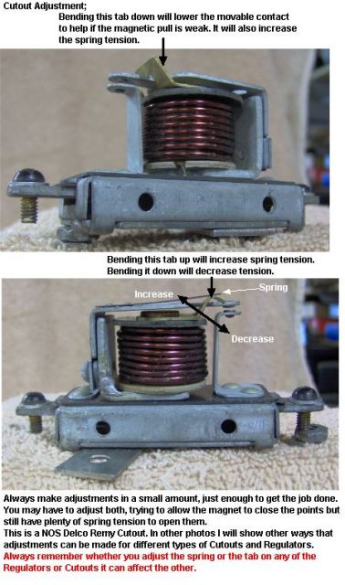
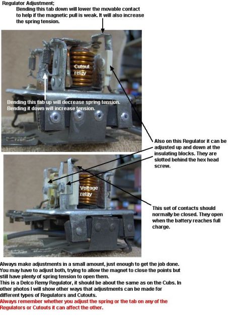
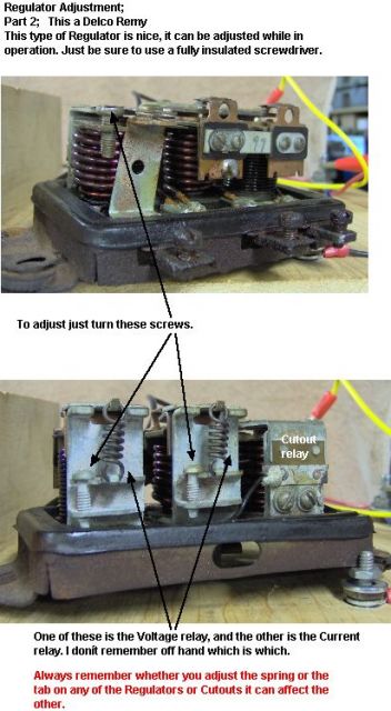
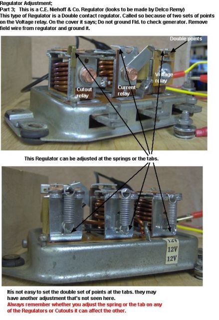
If the points are burnt they will need to be filed and then cleaned. When adjusting by the tabs keep the points as parallel as possible. I have bent them offset though if they were badly burnt on an edge.

Do not attempt to adjust them while the engine is running or there is battery voltage present.

Edit: Thanks to Bus Driver for pointing out that after the cover has been installed they need to be rechecked. They are heat sensitive.
Edit 2: Thanks to beaconlight for this info. The cover on affects the magnetic field is why it affects when installed.
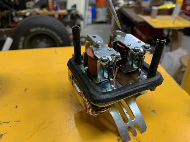
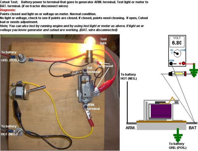
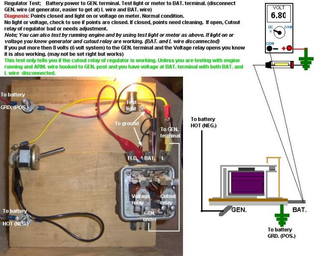
The first two photos show how to check a Cutout and the cutout relay of a Regulator.

The other photos show some of the possible ways to adjust them (depending how they are built) in an attempt to get them working.

Remember if you see some thing wrong let me know.

Image

Image

Image

Image

Image

Image

Re: Cutout and Regulator tests and adjustments

Posted: Wed Aug 01, 2012 2:53 pm
by Cecil
Mark, would it be possible to send me a copy of the test board and the circuit diagram for it. The diagram does not show completly in your post.

Re: Cutout and Regulator tests and adjustments

Posted: Fri Aug 03, 2012 9:55 am
by Rudi
Mark:

I like this one a lot. Going to be a lot easier to understand now. Excellent work and I am sure a lot of our members are going to be really happy that you took the time to do this for us. I know I certainly appreciate it :!: Thank you :)

Re: Cutout and Regulator tests and adjustments

Posted: Fri Aug 03, 2012 12:08 pm
by Bus Driver
Time at this moment did not permit reading all the accompanying text carefully. Voltage regulators are affected by the cover on the regulator. So after adjustments, it is very important to replace the cover and verify operating characteristics with the cover secured in place. I have had very few occasions where voltage regulators needed adjusting.

Re: Cutout and Regulator tests and adjustments

Posted: Fri Aug 03, 2012 5:28 pm
by birddog
Thanks for pointing that out Bus Driver. I did know that they were heat sensitive but I didn't think to mention it. I will add it to the post.

Re: Cutout and Regulator tests and adjustments

Posted: Fri Aug 03, 2012 8:55 pm
by awander
birddog wrote:Thanks for pointing that out Bus Driver. I did know that they were heat sensitive but I didn't think to mention it. I will add it to the post.


I'm not sure it is heat that is affecting them, as they do seem to change almost instantly when you install the cover.

Regarding your first post, and the advice many give that if it needs adjustment it is "done", the older Delco-Remy relays were made to be rebuilt and adjusted.

Thanks for the post!

Re: Cutout and Regulator tests and adjustments

Posted: Sun Dec 30, 2012 9:56 pm
by Hengy
I just wanted to bump this post to the top as I really found it helpful in troubleshooting my voltage regulator... Might be a good addition to the How To forum for the electrical system. Mark, I really appreciate your post!!

Mike

Re: Cutout and Regulator tests and adjustments

Posted: Sun Dec 30, 2012 10:14 pm
by Boss Hog
Cecil wrote:Mark, would it be possible to send me a copy of the test board and the circuit diagram for it. The diagram does not show completly in your post.

Right click on the pic and click on view pic and the complete pic will show
Boss

Re: Cutout and Regulator tests and adjustments

Posted: Sun Dec 30, 2012 11:17 pm
by beaconlight
The cover on affects the magnetic field is why it affects when installed.

Re: Cutout and Regulator tests and adjustments

Posted: Mon Dec 31, 2012 10:13 pm
by birddog
Thanks Mike.

Thanks beaconlight, I added that to the post.

Re: Cutout and Regulator tests and adjustments

Posted: Tue Jun 11, 2013 7:20 pm
by Gerry Powell
Good post.
When the cover is installed, make sure the gasket is in place at the base and the two screws have the nylon washers. The cover has to be isolated from ground or it will effect the coils. This prevents the cover from looking like a "shorted turn" to the coils.
Gerry

Re: Cutout and Regulator tests and adjustments

Posted: Wed Dec 30, 2020 12:02 pm
by Ojgrsoi
Thanks for the information on adjusting this regulator.

My question is, "To decrease the voltage output which way do you go with the points? Wider gap or closer?"

I have a 12V system in a 154. My issue is that the original voltage regulator points were just shot. I installed a new regulator and changed my brushes while I had everything opened up. Everything worked just perfect with the exception that I noticed the amp gauge seemed to be charging a lot. So I thought I would monitor the voltage and installed a volt gauge. The output is about 15V and does not change once warmed up. I had the battery tested and it tests good at the parts store. I have charged the battery overnight to make sure it was ready. I have checked all the wiring, everything is tight and battery cables are new. No change in the output.

So I bit the bullet and bought another voltage regulator since I could not find anything wrong. The new voltage regulator performs exactly like the first replacement. I drove the tractor around for over an hour so everything would have a chance to charge, get warm etc. Still the same.

Any and all thoughts are welcome.

Image
Image
Image

Re: Cutout and Regulator tests and adjustments

Posted: Wed Dec 30, 2020 6:11 pm
by birddog
I'm not sure which way you would adjust them. I just play with them until I get the result I want. Most often my adjustments were made to the cut out side because it wasn't charging at all.

Re: Cutout and Regulator tests and adjustments

Posted: Wed Dec 30, 2020 8:18 pm
by Glen
Hi,
It sounds like the system is working about right, the Cub service manual says the 12 volt system voltage for the Cub is supposed to be 13.6 - 14.5 volts when charging. 15 volts is a little more than that.
I don't have the 154 service manual, you could look in it to see what the voltage is supposed to be.

The charge rate on the ammeter normally goes down to small when the battery is fully charged, which is usually a few minutes after using the starter.

I have adjusted the voltage regulators on Cubs before.
If the one in your pics for a 154 works the same as a Cub regulator, to adjust the charge rate, or voltage output, you have to decrease the spring tension on the set of points that are on top of the coil of wire for the voltage.
It shows in the 5th pic down from the top. Slightly bend the bottom holder for the spring up to decrease the spring tension and voltage output. Be careful, it only takes a tiny bend to change the output.

In your 1st pic, you are pointing to the set of points that turns the system on and off, leave those like they are.
The other set of points, on the left in your 1st pic controls the voltage output of the system.

Also, I would remove some paint where the regulator mounts to the generator, it has to ground well.
The generator mountings may need paint removed also. :)