Engine brace
Posted: Wed Aug 29, 2012 9:48 am
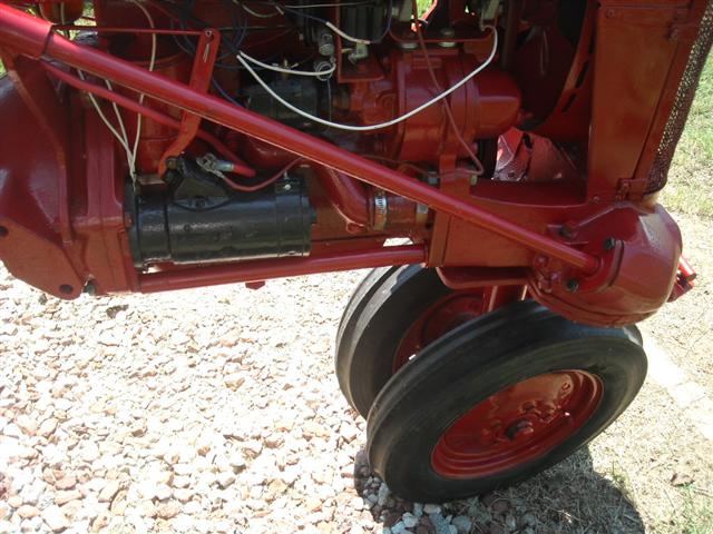
I have no idea how much the front engine mount on the right can move before it breaks but I have one cub with a welded ear. I thought to minimize movement i would want a straight connection between the front ear and the rear through a resonable thick peice of steel. I did not want any bends since that is a place for the brace to flex, I also did not want any welds mostly just for looks. So I came up with this design and I believe it will work well.
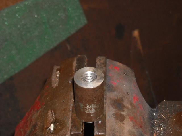
I took a peice of 1 inch cold rolled steel, drilled and tapped a 5/8 inch hole 1/2 way through. The other side has a 7/16 inch hole with a slight countersink. That piece acts as a nut and threads onto a 5/8 stud that replaces the 5/8 bolt going into the bolster. I then took a piece of DOM tubing, 1 inch dia, and cut for a tight fit between the rear engine mount and the peice of threaded CRS. A length of B-7 all thread rod, 7/16 , is pushed through the rear engine mound like the original 7/16 bolt, through the DOM tubing and threads into the 7/16 side of the CRS slug. The countersink or bevel helps guide the rod into the threaded part of the slug. Put a nut on the other end of the all thread rod and tighten. The DOM tubing and slug transfer the rearward movement to the rear engine mount. Any forward movement is tensioned by the all thread rod and that tension is transfered to the rear engine mount.
The rear mound hole and the front mount hole are not inline but offset by about 0.4 inches ( thanks to Rick Prentice for those numbers) as in the photos.
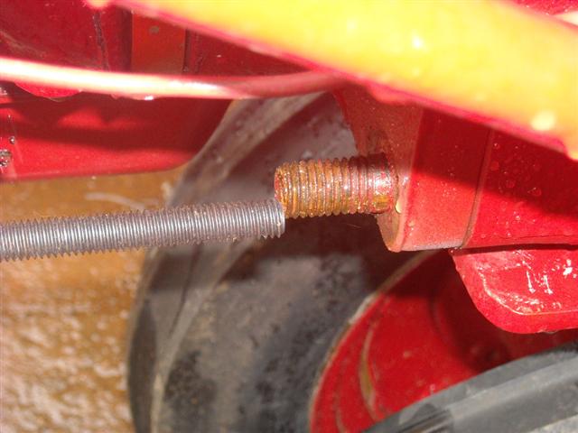
The all thread rod will move enough so that slight offset was not a problem. Quick and easy to make. The ends of the DOM tubing was given a tiny bevel or angle to allow for that offset.
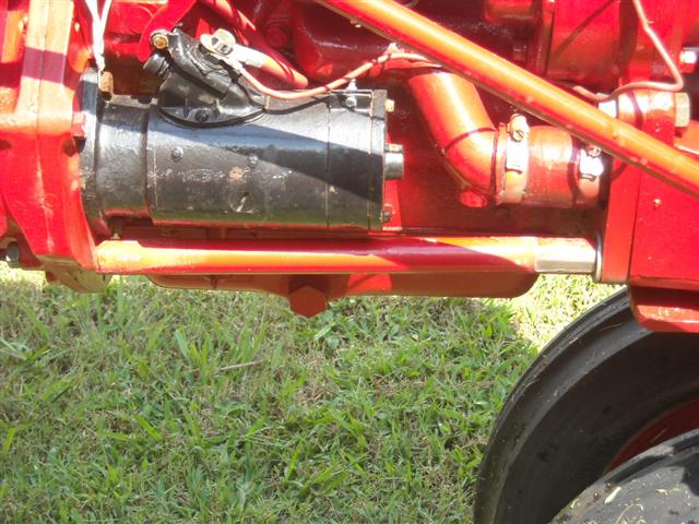
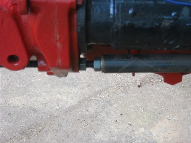
Another way is to cut the DOM tubing short and use two nuts to help direct the force as in this photo. Easier, less fitting, but does not look as nice.
I took a peice of 1 inch cold rolled steel, drilled and tapped a 5/8 inch hole 1/2 way through. The other side has a 7/16 inch hole with a slight countersink. That piece acts as a nut and threads onto a 5/8 stud that replaces the 5/8 bolt going into the bolster. I then took a piece of DOM tubing, 1 inch dia, and cut for a tight fit between the rear engine mount and the peice of threaded CRS. A length of B-7 all thread rod, 7/16 , is pushed through the rear engine mound like the original 7/16 bolt, through the DOM tubing and threads into the 7/16 side of the CRS slug. The countersink or bevel helps guide the rod into the threaded part of the slug. Put a nut on the other end of the all thread rod and tighten. The DOM tubing and slug transfer the rearward movement to the rear engine mount. Any forward movement is tensioned by the all thread rod and that tension is transfered to the rear engine mount.
The rear mound hole and the front mount hole are not inline but offset by about 0.4 inches ( thanks to Rick Prentice for those numbers) as in the photos.
The all thread rod will move enough so that slight offset was not a problem. Quick and easy to make. The ends of the DOM tubing was given a tiny bevel or angle to allow for that offset.
Another way is to cut the DOM tubing short and use two nuts to help direct the force as in this photo. Easier, less fitting, but does not look as nice.