winter project
Posted: Tue Feb 26, 2013 9:41 pm
So, I decided to put hydraulic controls on my 54 blade this winter so I could do a better job grading driveways, and thanks to my new internet connection and BigDog's quick response to my photo host request, I am able to share. I put the cub in the shop, and started on the blade, and then had to wait for parts, so I decided to replace the magneto oil seal while I waited. This led to replacing the radiator, so I had to clean up the front of the engine, and so on. Anyway, I finally got the hydraulics for the blade done, so I thought I would post some pics.
I searched on the forum, and found all sorts of information on tapping into the TC hydraulics, so that was no problem. I also found several topic about hydraulic angle cylinder conversions that confirmed my ideas, and provided some new ones.
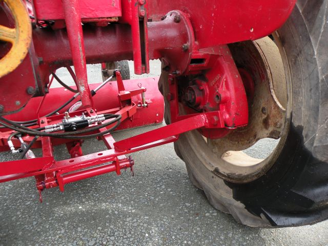
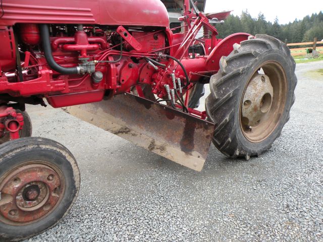
first of all this is the custom mounting system I use to belly mount the blade. I mounted it with the drawbar reversed, and didn't really think it looked very solid. If you can't tell, I just changed the oil in the finals. I decided to try Hytran in the finals and tranny this time.
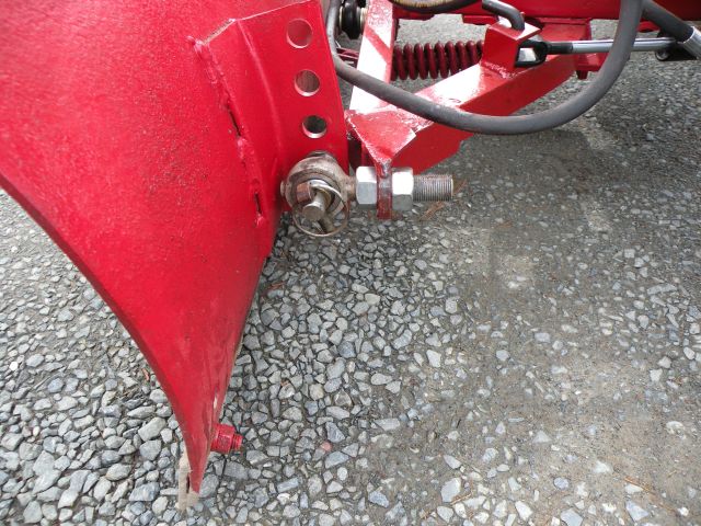
This is the first modification I made to the blade. I cut off the tab on the table that the blade mounting pin goes through. Then I welded on a bracket to mount this rod end from a three point hitch. You can also see here that I used the same cylinder and brackets that others on the forum have used to angle the blade.
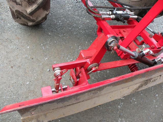
This end was a little more complicated. I first slotted the bracket on the blade so it could slide up and down to tilt the blade. Then I briefly considered mounting the cylinder vertically to move the blade up and down directly, but quickly decided that there would be interference issues with the operators platform. Besides that it would look goofy. So, I had to come up with this rocker system to mount the cylinder horizontally. This is where I spent most of my time and hair pulling. It still doesn't work quite the way I would like, but it is functional. The tilt cylinder, by the way, is the same size as the angle cylinder (1.5"x8"), but I used one with spherical rod ends.
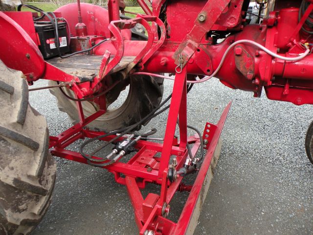
This shot shows generally how things are put together. The valve on top of the grader frame is a line relief/ cross relief/ cushion valve that protects the angle cylinder and hoses should I have a runin with an immovable object. The original release spring on the bottom of the blade also remains operable.
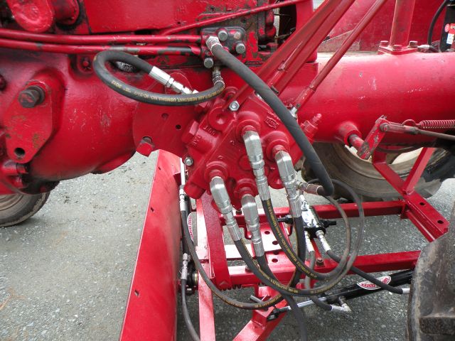
This is the control valve that I scavenged from my dad's shop to save a few dollars. It is a Cross loader valve from a tractor, and is big for this application, but the price was right. It has a built in PRV that I was able to set to 1200# using a cheap hydraulic gage with an inline tee, and yes I did check to make sure it was open center before installing it. I found the bypass block on E-bay. I went with this one because it didn't have that extra ear on the back. It fits well, and came with gaskets and bolts, but the faces are not machined. So far no leaks though. I had to remove the pushrod to the rear rockshaft, because it was in the way of the controls.
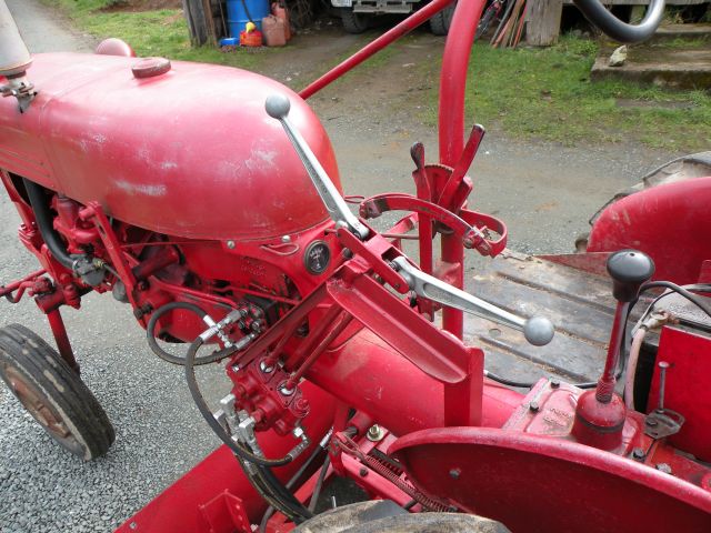
This is the control setup that I came up with to keep the valve close to the hydraulics and minimize the hose mess. I took the levers off the valve body, and attached the short link shackles to a 1/2" pushrod. I turned the rods to a slip fit in bronze bushings that are mounted to the bracket near the levers. This system put the levers at a strange angle that makes them hard to reach, and not very intuitive to operate. It's probably the first thing I will change. I haven't had much seat time with it yet, but it is very frustrating, because I sometimes run a grader at work, and this setup doesn't operate the same way. More practice will surely improve my abilities.
The blade tilts more in one direction than the other, but that can be changed by unbolting and repositioning the rod end on the stationary side.
All of the new parts, including the hoses, came from The Surplus Center. Their prices are very reasonable, and although some of the chinese fittings didn't seen to have consistent pipe threads, I haven't had any leaks yet (except for the one or two fittings I forgot to tighten). Time will tell whether this was as good investment or not, but it was fun, and gave me some motivation to fix other things that needed attention.
I searched on the forum, and found all sorts of information on tapping into the TC hydraulics, so that was no problem. I also found several topic about hydraulic angle cylinder conversions that confirmed my ideas, and provided some new ones.
first of all this is the custom mounting system I use to belly mount the blade. I mounted it with the drawbar reversed, and didn't really think it looked very solid. If you can't tell, I just changed the oil in the finals. I decided to try Hytran in the finals and tranny this time.
This is the first modification I made to the blade. I cut off the tab on the table that the blade mounting pin goes through. Then I welded on a bracket to mount this rod end from a three point hitch. You can also see here that I used the same cylinder and brackets that others on the forum have used to angle the blade.
This end was a little more complicated. I first slotted the bracket on the blade so it could slide up and down to tilt the blade. Then I briefly considered mounting the cylinder vertically to move the blade up and down directly, but quickly decided that there would be interference issues with the operators platform. Besides that it would look goofy. So, I had to come up with this rocker system to mount the cylinder horizontally. This is where I spent most of my time and hair pulling. It still doesn't work quite the way I would like, but it is functional. The tilt cylinder, by the way, is the same size as the angle cylinder (1.5"x8"), but I used one with spherical rod ends.
This shot shows generally how things are put together. The valve on top of the grader frame is a line relief/ cross relief/ cushion valve that protects the angle cylinder and hoses should I have a runin with an immovable object. The original release spring on the bottom of the blade also remains operable.
This is the control valve that I scavenged from my dad's shop to save a few dollars. It is a Cross loader valve from a tractor, and is big for this application, but the price was right. It has a built in PRV that I was able to set to 1200# using a cheap hydraulic gage with an inline tee, and yes I did check to make sure it was open center before installing it. I found the bypass block on E-bay. I went with this one because it didn't have that extra ear on the back. It fits well, and came with gaskets and bolts, but the faces are not machined. So far no leaks though. I had to remove the pushrod to the rear rockshaft, because it was in the way of the controls.
This is the control setup that I came up with to keep the valve close to the hydraulics and minimize the hose mess. I took the levers off the valve body, and attached the short link shackles to a 1/2" pushrod. I turned the rods to a slip fit in bronze bushings that are mounted to the bracket near the levers. This system put the levers at a strange angle that makes them hard to reach, and not very intuitive to operate. It's probably the first thing I will change. I haven't had much seat time with it yet, but it is very frustrating, because I sometimes run a grader at work, and this setup doesn't operate the same way. More practice will surely improve my abilities.
The blade tilts more in one direction than the other, but that can be changed by unbolting and repositioning the rod end on the stationary side.
All of the new parts, including the hoses, came from The Surplus Center. Their prices are very reasonable, and although some of the chinese fittings didn't seen to have consistent pipe threads, I haven't had any leaks yet (except for the one or two fittings I forgot to tighten). Time will tell whether this was as good investment or not, but it was fun, and gave me some motivation to fix other things that needed attention.

 Very nicely done Glenn. Great project and nicely executed. I really enjoy seeing what guys can come up with when they put their mind to it.