Ignition tests schematics (large post)
Posted: Mon Jul 23, 2012 2:39 pm
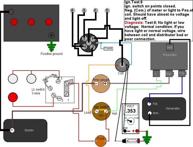
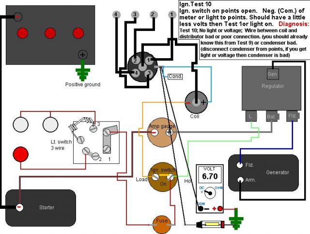
The schematics that I’ve drawn, are I believe, the way the Cub is wired from what I see on my Cub and what's in the operators manual. It is set up as a 6 volt positive ground. If you want to test a Neg. ground system just reverse the leads on your meter. (test light doesn’t matter)
Don’t assume I’m correct. If I have something wrong or I should add a test let me know. Thanks to Landreo and Eugene for expressing their interest in a schematic version and for their input. And as before, per brichters request, I tried to keep it simple.
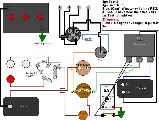
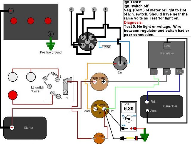
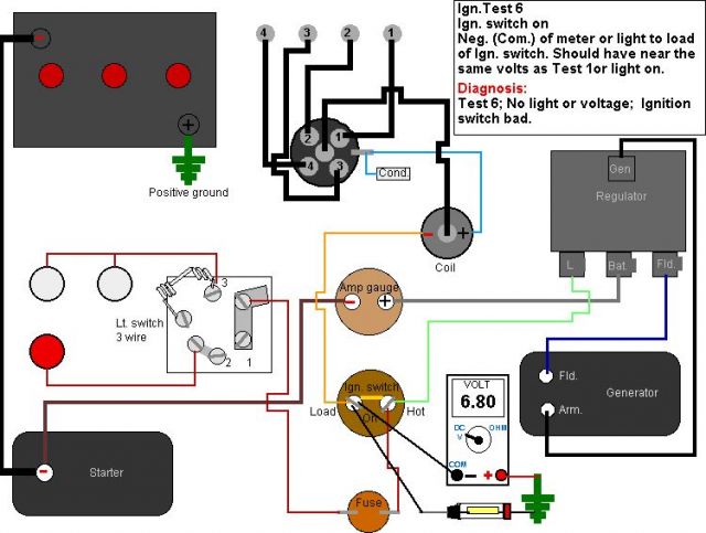
These tests shown here are for a no spark scenario with a distributor ignition. I assume that if you know you have no spark that you do have battery voltage. These tests should work on almost any similar engines, including single cylinder. The sequence may differ slightly and some may not be needed depending on how the unit is wired. Also remember, each Test diagnosis is based on having passed the previous test. Make sure you always have a good connection with the meter or the test light.
The Pos. of the meter or one side of a test light goes to the Pos. (+) post of the battery or to a good ground, for all the tests shown here. For all of these tests a volt - ohm meter or a test light will work.


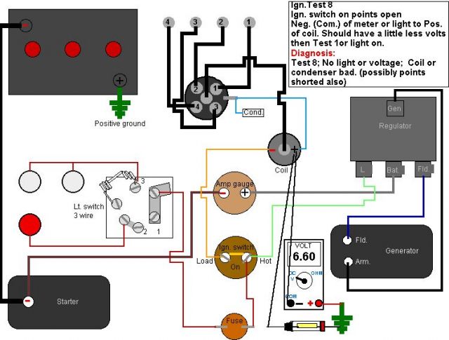
If after the tests you can’t find the problem, then the condenser or the coil is bad. I believe how to check these may be in the “HOW TO FORUM”
Don’t assume I’m correct. If I have something wrong or I should add a test let me know. Thanks to Landreo and Eugene for expressing their interest in a schematic version and for their input. And as before, per brichters request, I tried to keep it simple.
These tests shown here are for a no spark scenario with a distributor ignition. I assume that if you know you have no spark that you do have battery voltage. These tests should work on almost any similar engines, including single cylinder. The sequence may differ slightly and some may not be needed depending on how the unit is wired. Also remember, each Test diagnosis is based on having passed the previous test. Make sure you always have a good connection with the meter or the test light.
The Pos. of the meter or one side of a test light goes to the Pos. (+) post of the battery or to a good ground, for all the tests shown here. For all of these tests a volt - ohm meter or a test light will work.
If after the tests you can’t find the problem, then the condenser or the coil is bad. I believe how to check these may be in the “HOW TO FORUM”