put me on to the concept of a diode in place of the cutout, though he never had actually done it. What I really wanted to do, in my effort to keep my "Blue Ribbon Cub" as close to original as possible, was gut the existing Delco Remy cutout and "hide" the cutout inside it, even though once the hoods on it you can' tell it anyway...it was just a personal thing.
After looking back through my Brillman catalog, I ordered the D100 Cutout relay from Brillman for slightly less than $30, after talking with Jim Brillman on the phone to see if he bought my crazy idea of putting the new cutout relay in the old can. He seemed to think there was more than enough room to make it work and it should work out well. Heck of a ncie guy and I enjoyed talking to him on the phone. I've bought stuff from him before, but never actually spoke with him. Very sharp!
http://brillman.com/store/d100-cutout-relay.html
Last night about 9:10 after finishing my garden chores for the evening I got my second wind so to speak and set in on making the cutout relay swap. First off let me apologize for the crappy pictures. It was dark in my shop, I was tired after working on all day and working the garden and my pictures came out terrible but you should be able to get the idea.
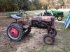
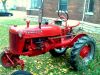
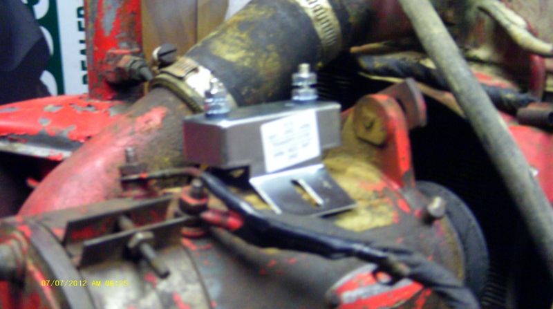
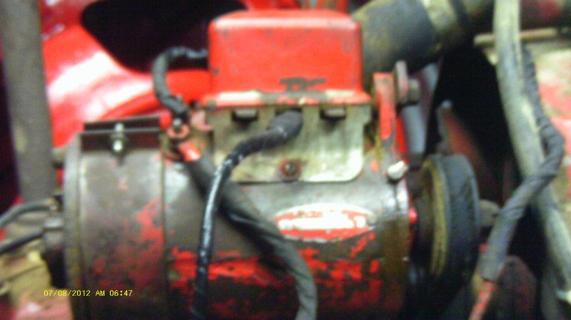
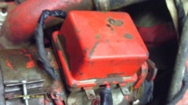
First a picture from several months ago showing what I had originally...
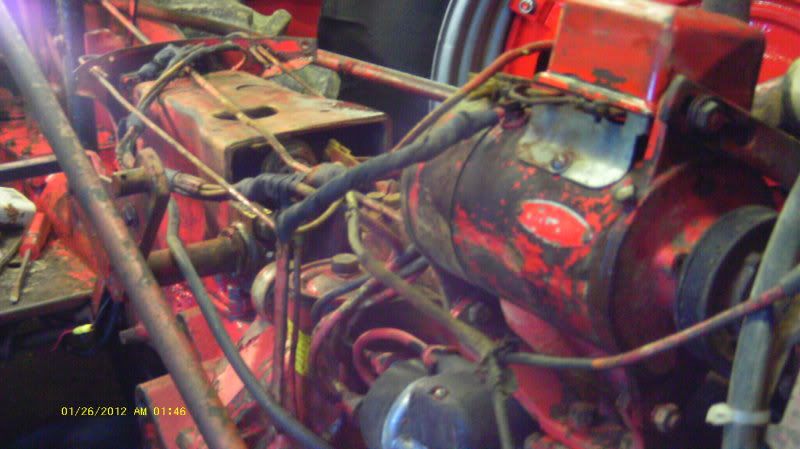
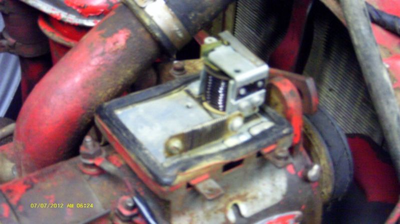
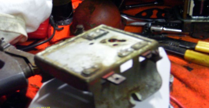
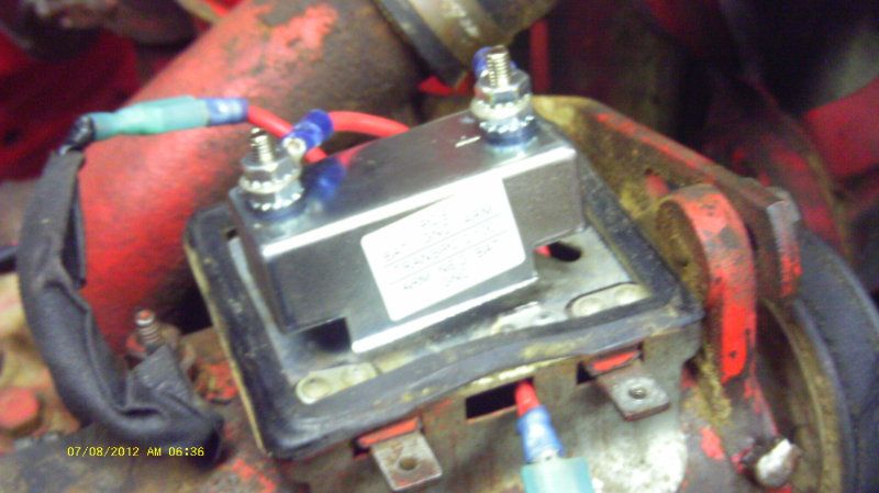
The first picture from last night with the hood off and the lid taken off the cutout...
My idea is really better than I thought, as the feet on the D100 won't line up with the mounting holes in the generator anyway. It's footprint is much smaller...
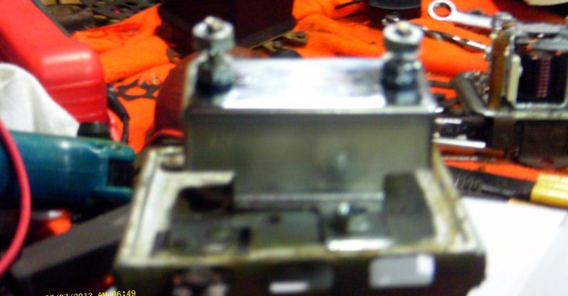
Using my craftsman dremel tool I cut all the guts out of the cutout. I'll be able to make use of the existing mounting hole for the coil as an opening to get my new wiring into the can...
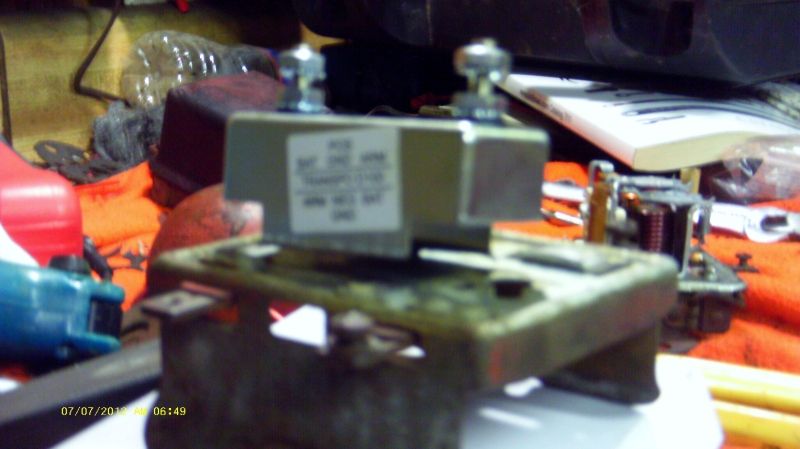
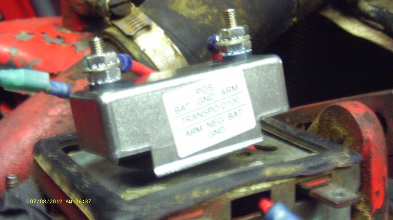
The D100 has small wiring decal on it, ARM to positive and BAT to negative for positive ground and vice-versa for negative ground...
I did have to cut one foot off the diode and cut the side out of the other. It let me keep it centered up enough in the can to clear the tapped hole in the bottom for the cover screw...
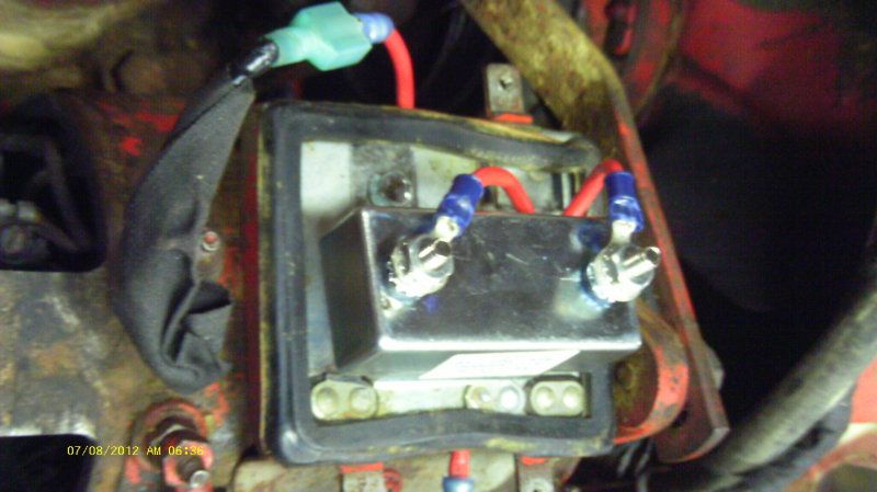
Wiring is really simple. I cut the ends of the existing wiring and added female spade connectors. If I ever need to take generator off I can just unplug everything. The BAT wire connectors to the NEG side of the diode and the ARM lead from the generator connectors to the (+) side of the diode. Conventional "modern" negative ground sytems are the exact opposite.
Didn't show it here for clarity, but I did wrap the terminals of the diode up with insulating tape prior to bolting on the cover. As well as taping up the spade connectors once I put a little heat on them to shrink the insulation...
Completed with the lid back on it...
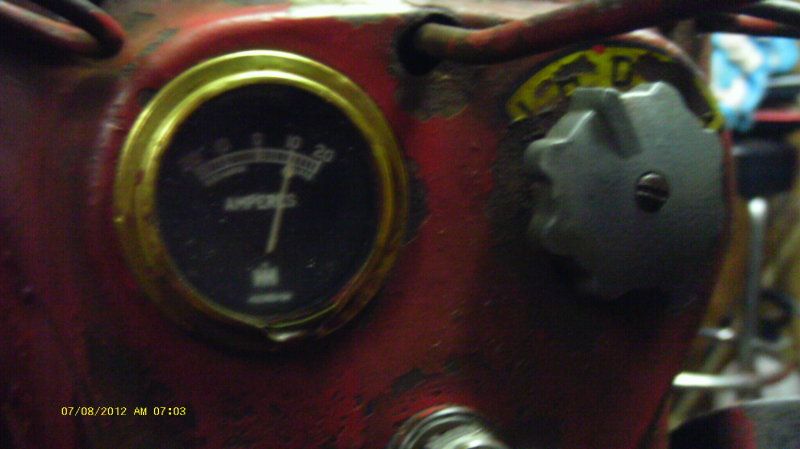
And the moment of truth, charging on Low...
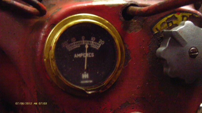
And charging nicely on High...
Hope this helps someone else along the way. Total cost was a tad over $30.00 and it took longer to remove and reinstall the hood that it did to make the swap...I was on the front porch swing enjoying a nice cigar and cold drink by 10:30 last night