My dimensions are different that Ron’s, and my attachment to the tractor is also different, but the basic idea is still the same.
Lets start with a list of materials, cut to length dimensions given:
2" x 2" x 3/16" angle iron is the basis. I’m trying 3/16" instead of 1/4" to save on cost and weight. I believe that it should handle anything that the tractor can pick up w/o lifting the front end. As long as its not abused, I see no reason for it not to work just fine.
2x2 angle, 36" long (2)
2x2 angle, 25" long (2)
2x2 angle 18 ½" long (2 or 3 as preferred)
2x2 angle, 2" long (4) (2 will be cut down to 2" x 3/4" )
3/8" x 2" 3" long (2)
½" x 4" grade 5 bolt (1)
½" x grade 5 bolt (2)
5/8" x grade 5 bolt (2)
Tools needed:
Cutting torch
Welder w/ appropriate equipment.
Cutoff saw. (Nice but not necessary if you have a torch)
4" angle grinder or the like
½" drill bit
5/8" drill bit
measuring tape
square w/ 45 deg capabililty
marking chalk
hammer and center punch
SAFETY GLASSES! (More about that later)
Having cut all of the pieces to length, all that is really required is drilling holes, some minor cutting, fitting and welding, and then lots of grinding.
Lets start with the brackets. I've made my brackets differently than Ron's to permit quick removal of the carrier without wrenches. I can put it on or take it off in under 60 seconds using nothing more than my hands.
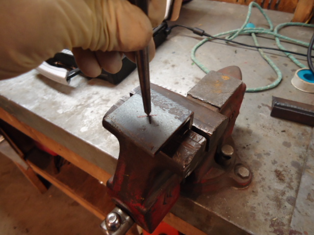
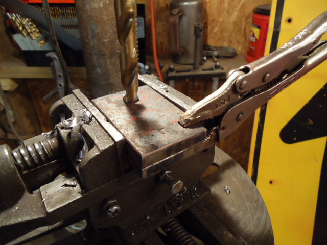
Take one of the 2x2x2 pieces and draw an "x" on one side from corner to corner to find center.
Center punch it, then drill it out to 5/8". I like to start out w/ a 5/16" bit to ensure I'm on my center and then drill it out to 5/8.
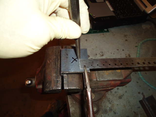
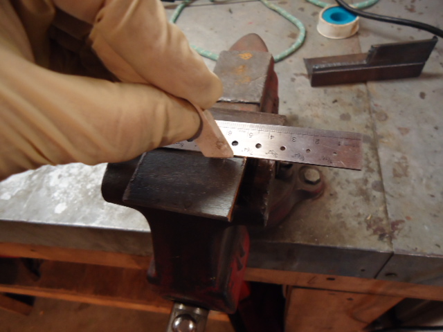
On the other leg of the angle, again find center, only this time center punch above the center, towards the edge of the angle, 5/8" down from the edge. This is an important measurement, as it will allow clearance for the hinge to work. Starting with a pilot hole, drill this out to 1/2".
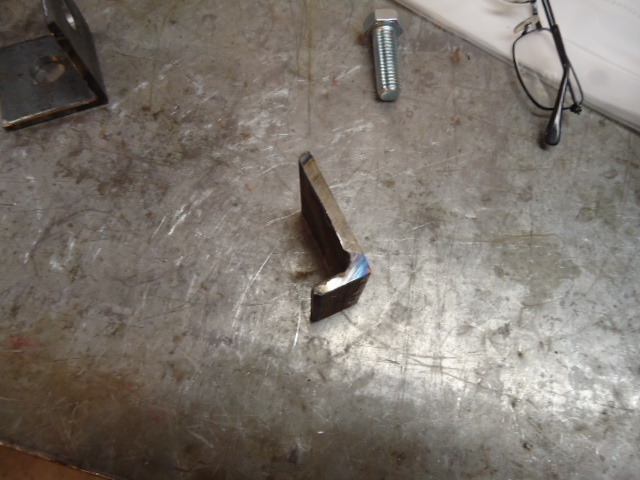
Now, take another piece of angle, and cut one leg to a height of 3/4" using a torch or handheld cut off tool Make sure the cut edge is square. I prefer to cut it a tad long, then grind it to a chalked line to be sure.
The finished leg should look like this.
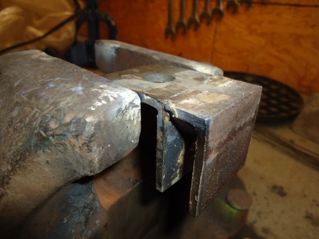
Now, grind a chamfer on the edge of the short leg before welding. Most of the weld will be ground back off to allow the bracket to set flat on the drawbar so the chamfer is important to have adequate weld remaining. Weld the two pieces together as shown. The 5/8" hole is on the left in the picture.
Place the parts in a vise, and making sure everything stays square, tac it, then weld it together inside and out.
Grind off the weld on what will be the bottom of the bracket.
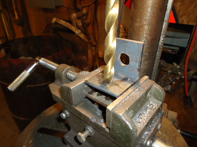
Then using the first 1/2" hole as a guide, drill through the other piece just added.
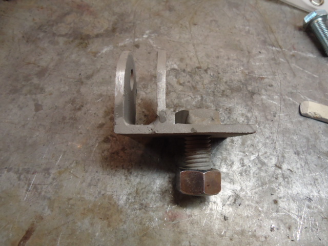
Next, cut off the corners and round them down with a grinder, as shown. This is most critical for the small piece that you just added, as it must have clearance for the framework to come.. You'll see in a bit and it will all make sense. Trust me.
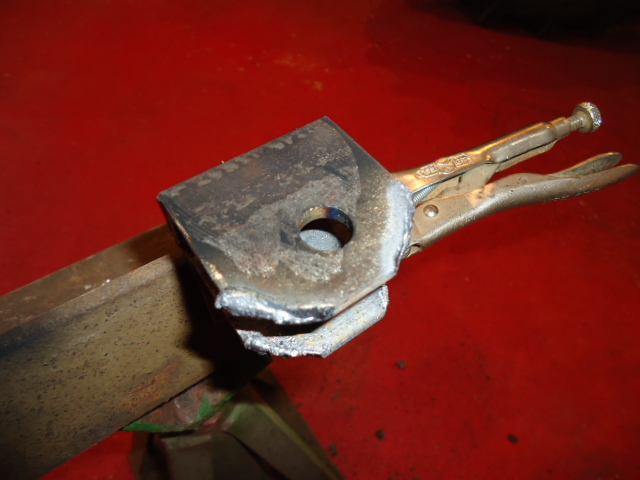
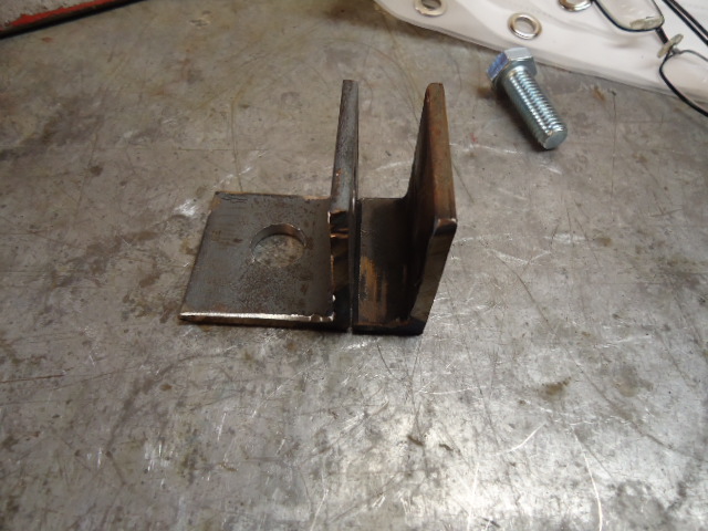
Next, put the 5/8" bolt through the hole from what would be the top of the bracket, then clampt the BOLT in a vice, keeping the bracket flush against the underside of the bolt head. (keeping the bolt at 90 degrees to the plate it is through.) Weld the bolt in place. (This is optional, but it makes putting the brackets on a one wrench deal.) The finished bracket should look like this. If it does, do the whole thing one more time and you'll have the brackets done.
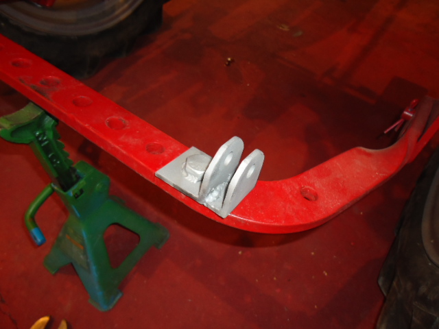
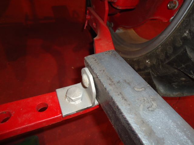
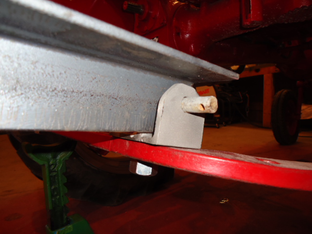
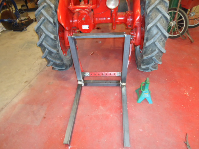
This is how they will be put on the drawbar.
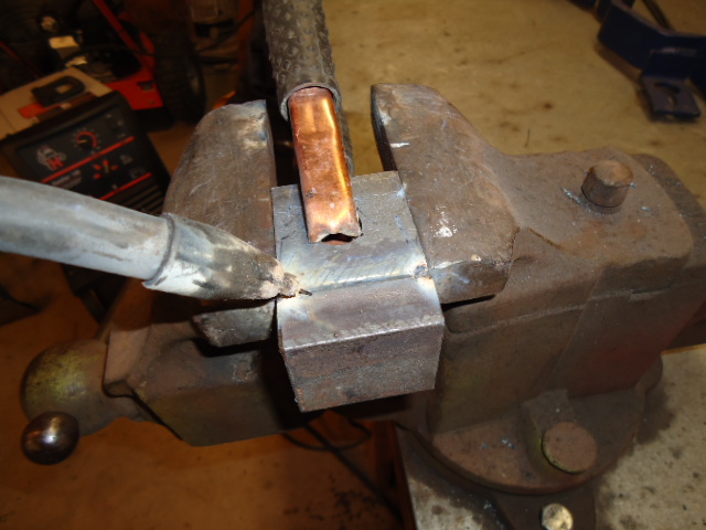
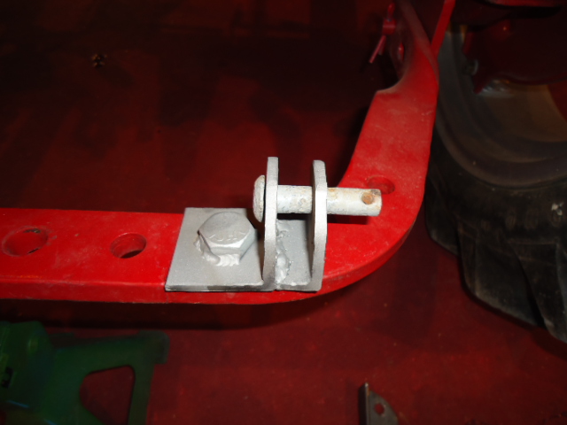
Here is how a pin will be used instead of a bolt, allowing quick removal. (this pin is actually too long, but it was handy.) You can use just a simple angle, but that will require use of a bolt and a nylon lock nut... which means multiple wrenches and time spent putting on or taking off the carrier.
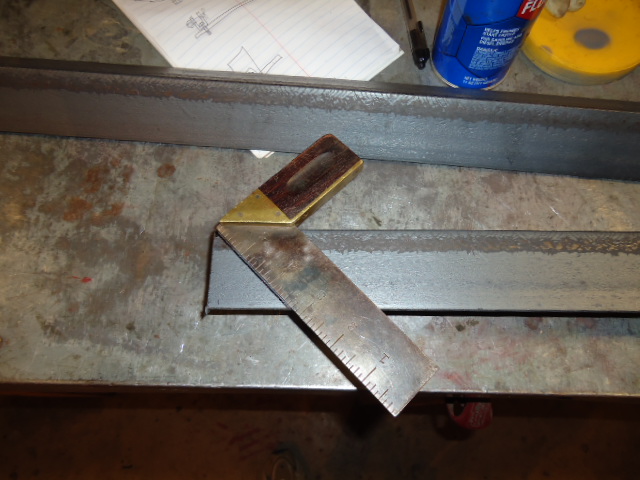
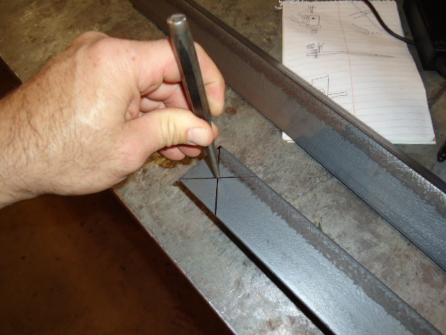
That was the most difficult part of the entire project. The rest is easy. Now lets move on to the actual supports. Start with 2 36" long pieces of 2x2 angle. Using a 45 degree, strike an X on one end, using the very corners as your starting point for the lines, to find a center point. Center punch that point, and drill a 1/2" hole.
Mark a radius on the corner of the angle. As you see, duct tape works for most anything! (Something that puts a nice radius is all you need, but it must allow the end of the angle to clear the bracket when the carrier is lowered. You'll see what I mean in a bit.
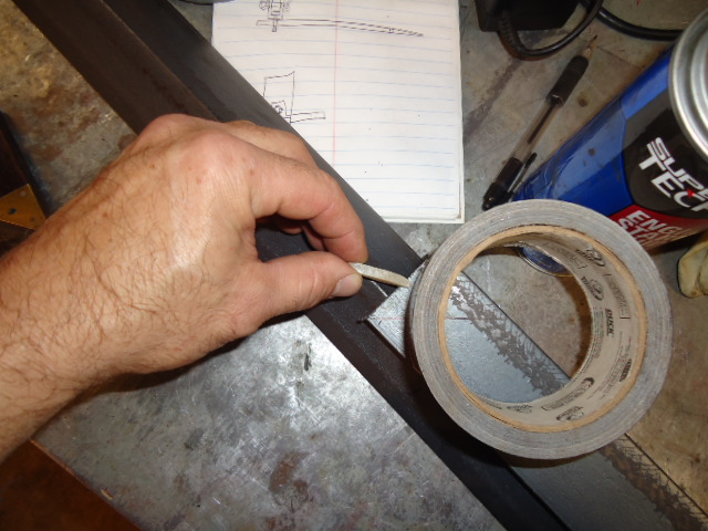
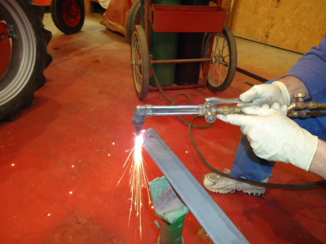
Grab the torch and hack off the corner. You can take off some other corners of the angle to make it more "user friendly" if you want to. I did later, as an afterthought, and it wasn't a problem, but you could do it all at once and save some time.) Before anyone has a cow, YES I did have on rubber gloves. I was wearing good leather ones for the pic I was going to use, but was blurry..I got in a hurry and forgot to put them back on after handling the camera.
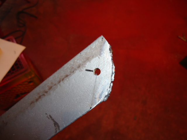
Grind the edges smooth and test fit to the bracket. It should "hinge" without interverence.
Make another one, but remember, it MUST BE A MIRROR IMAGE of the one you made, not JUST LIKE the one you made. Think about it.
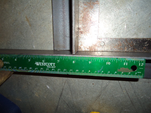
Next. lay everything out and scribe a line 8" on the top surface, in from the hinge end of the 36" long angles. Do that on the inside surface also. Weld the 25" upright sections onto the tops of the 36"angles, making sure that everything is square. The "back" edge of the angle, where the wood will be touching, should be 8" from the hinge end. The picture shows how it should be welded. Looking at a "finished picture" will give you a better idea of the orientation of the pieces.
Pay special attention to keeping everything square. Your inside dimensions should all be 18 1/2", to accomodate the cross pieces. Weld the cross pieces in as shown. Tac, check for square, tac some more and check again... before you make your finish welds.
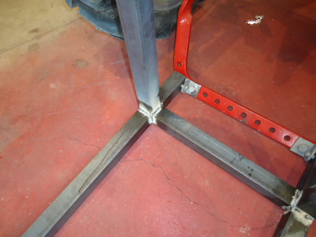
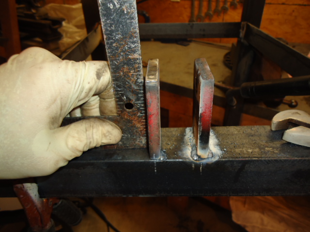
Now on to the top attaching point. Take the two 3/8" by 2x3 pieces adn centerpunch ONE of them 5/8" in from one end, in the midline of the piece. Clamp the two pieces together firmly, and starting with a pilot hole, drill them out to 1/2". Make sure that the pieces are flush on the end that will be welded to the carrier. (opposite the end with the holes), before you drill.
Weld the two pieces in place. The INSIDE surface of the left piece is 8" from the left end of the top 18 1/2" piece. The INSIDE surface of the right piece is 9" inches from the right end of the top 18 1/2" piece. Make sure they are square, tac and weld.
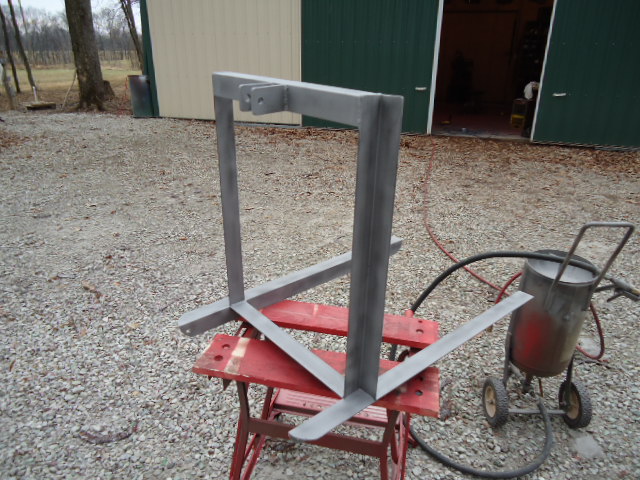
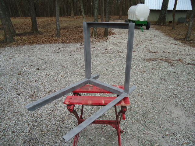
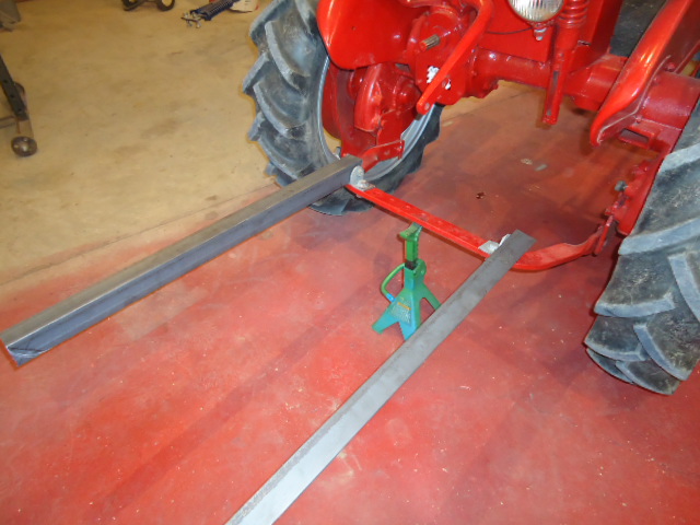
You now have the bulk of the carrier done. It looks like this
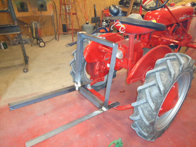
You could add another 18 1/2" inside piece between the two 36" pieces closer to the end if you chose, but I believe the wood that I'm going to install will suffice.
I'll be using 1/4" carriage bolts and treated 44" long 2x10 boards on the bottom and back. It would be easiest to have drilled the holes before welding everything together, but 1/4" holes aren't too tough to add and I wasn't sure what boards I was going to use. The 10" wide boards work out perfectly on the bottom, going just to the edge of the 36" pieces. You'll see that I rounded several other corners, and those that I didn't, I did grind smooth. I'll post more pics in a few days when I finish painting and installing the wood.
This is a pretty simple project, and hopefully, inspires some to build one. I understand not everyone has a shop or tools with which to do this, and if you fall into that category but still want one, drop me a line and I'll see what I can do.